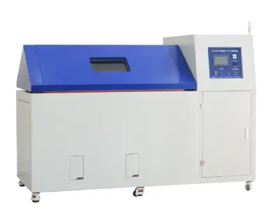
T-Cyclic Corrosion Test (CCT&CRH) Cabinets
For most artificial accelerated tests in laboratory, getting a consistent testing result with outdoor is the most important purpose. Prior to cyclic corrosion testing, conventional salt spray (a continuous salt spray at 35°C) was the most popular way to simulate corrosion in a lab. Because conventional salt spray methods failed to simulate the natural wet/dry cycles of the outdoors, test results frequently provided poor correlation to outdoors. In order to better simulate the complex and variable external natural environment, cyclic corrosion test has gradually been considered as an important and effective method for the life assessment of industrial products.
The Cyclic Corrosion Test Cabinets is also called CCT&CRH Cabinets. Some industrial products need to be exposed to repeated cyclic salt spray, dry, and static environment with high humidity and low humidity. These tests were initially checked between several test chambers manually. The multi-functional Cyclic Corrosion Test Cabinets solves this problem well, and realizes the automatic test for these cycles in a chamber.
In a typical cyclic corrosion cabinet, all specimens are exposed to a series of different environments in a repetitive cycle that simulates the outdoors. Simple cycles, such as Prohesion, may consist of cycling between salt fog and dry conditions. More sophisticated automotive methods may ask for multi-step cycles that incorporate humidity, dry or air condensation, along with salt spray and dry-off.
Within the chamber,users can cycle easily through a series of the most significant corrosion environments. More complex test cycles can easily be programmed with the controller. Bluged CCT&CRH Cabinets contain salt spray, Prohesion, and 100% humidity for most middle automotive tests.
The Cyclic Corrosion Test Cabinets developed by Bluged sets and controls various parameters through the touch screen, and combines multiple tests associated with corrosion, humidity temperature and high humidity, low temperature and low humidity; during dry and drying to simulate a variety of cyclic corrosion tests. The device can conduct neutral salt spray test (NSS), acetic acid salt spray test (AASS), copper accelerated acetic acid salt spray test (CASS), dry heat test, drying test and standard atmospheric environment test separately.
Standards
- ISO 4611: Plastics — Determination of the effects of exposure to damp heat, water spray, and salt mist.
- ISO 7253: Paints and varnishes — Determination of resistance to neutral salt spray (fog).
- ISO 9227: Corrosion tests in artificial atmospheres — Salt spray tests.
- ISO 11493: Corrosion of metals and alloys — Accelerated testing involving cyclic exposure to salt mist, “dry” and “wet” conditions.
- ISO/DIN EN 16151: Corrosion of Metals and Alloys — Accelerated Cyclic Tests With Exposure to Acidified Salt Spray, “dry” and “wet” Conditions.
- ISO 16701: Corrosion of metals and alloys — Corrosion in artificial atmosphere — Accelerated corrosion test involving exposure under controlled conditions of humidity cycling and intermittent spraying of a salt solution.
- ASTM B 117: Standard Practice for Operating Salt Spray (Fog) Apparatus.
- ASTM E 368: Standard Practice for Copper-Accelerated Acetic Acid-Salt Spray (CASS) Testing.
- ASTM B 380: Standard Test Method for Corrosion Testing of Decorative Electrodeposited Coatings by the Corrodkote Procedure.
- ASTM G85-11: Standard Practice for Modified Salt Spray (Fog) Testing.
- ASTM D 1735: Standard Practice for Testing Water Resistance of Coatings Using Water Fog Apparatus.
- DIN 50021: Salt Spray Testing.
Features
1. Cabinet Material
- The inner cabinet is welded with imported 1mm high corrosion preventive pure titanium panel, and the outer cabinet is made of 1.2mm stainless steel, with the surface treated with baking paint.
- The top angle is 110°, which can prevent condensate water during the test from dropping to the specimen surface and affecting testing results. There is also a transparent observing window made of tempered glass (400mm x 280mm).
- Cabinet Cover Lifting Operation: The cabinet cover lifting is controlled by an air cylinder. The lifting speed can be adjusted by air pressure. The operation is easy.
- The outer cabinet is sealed with thermostability and corrosion preventive silicone strips to ensure that the corrosive gas in the cabinet does not leak.
- Sample Holder:
- The upper sample holder is a U-shaped slot strip made of corrosion preventive insulating resin material, with evenly distributed bayonets on both sides of each slot strip to ensure that the angle of the placed test pieces meets the standard requirements (20° ± 5° to the vertical plane).
- The lower sample holder is a solid and dismountable mesh platform, which is specially used to place workpieces, special-shaped samples, or large samples. The platform surface mesh can prevent the accumulation of solution after fog falling, which is also beneficial for air circulation in the instrument.
- The mesh is made of reinforced glass steel and can withstand up to 600kg (when the samples are evenly distributed). The platform is placed above the heating layer at a distance of about 150mm from the bottom to facilitate ventilation.
- Electrical Components:
- The electrical control part and the working room are left and right separated; the left is the working room, and the right is the electrical control part. The water and electricity separation structure effectively prevents water from entering the electrical control part to damage the accessories,which is safe and reliable.
- The whole instrument is a desktop structure. The bottom of the instrument is welded with a frame structure with stainless steel square tubes. The bottom is equipped with the mobile Fuhna foot cups to move and position the instrument.
- The rear of the instrument is distributed with a working room drainage hole, a saturation barrel drainage hole, a fog drainage hole, a test hole, and an automatic liquid inlet hole.
2. Spray Fog System
- Spray Solution Supply System: The configured spray solution is stored in the water tank (external type, volume of about 300L) and the spray solution in the water tank is absorbed by the peristaltic pump and supplied to the nozzle. Each nozzle can independently control the supply amount of spray solution. This design avoids nozzle crystallization caused by the traditional siphon spray method.
- Spray Amount Adjustment System: Self-developed patented technology to precisely adjust the spray amount.
- The peristaltic pump is used to precisely control the flow of spray solution, and the high-precision stepping motor drives the peristaltic pump to work. The operator can adjust the spray solution supply according to the required spray amount, so as to achieve constant spray amount control and water saving.
- The spray pressure of the nozzle can be precisely controlled by the coordinated secondary voltage control, which can achieve the precision atomization and spray the salt fog to the working room to ensure the uniform settlement of the spray solution.
- The spray amount adjustment baffle is installed above the nozzle, and its opening can be adjusted to control the spray amount.
- Spray Nozzle: Self-developed patented anti-blocking nozzle, which is made of pure titanium corrosion resistant material, and it can control the spray amount and angle.
- Spray Amount Monitoring: On the left and right sides of the working room, two Ø100mm fog collectors are installed at 170mm away from the cabinet wall and about 1/3 of the height from the bottom of the cabinet. The end of the funnel is extended to the outside of the cabinet with a hose. A measuring cylinder with a volume of 50ml is installed on the outer wall of the cabinet to monitor the spray fog amount.
- Spray Fog or Drain-away Fog: Spray fog can be done by manual or setting a program. Draining-away fog can also be run by manual or setting a program (feed compressed air to the working room then drain away the fog from the working room quickly).
- Saturation Pressure Barrel: Also called air filtration barrel, it is constructed with SUS304 stainless steel and is designed to ensure a constant saturated air and adjusted temperature. The pressure barrel is used with a water level control device, a heated device and a temperature control system. At the same time, a circle of holes is set on the circumference of the barrel, and the water level can be controlled through them by the fine hole at the bottom, which lets the bubbles out through the holes. This ensures the continuous water supply and keeps the water level of the barrel constant in the spraying state. At the same time, the saturation barrel has the function of liquid level monitoring and liquid level limit alarm.
3. Temperature/Humidity Control System
- Temperature/Humidity Control System
- Salt Spray Cycle Heating: A heating device with titanium tube armouring is installed on both sides of the bottom of the inner cabinet. It adopts thermal radiation heating mode and P.I.D control heating amount, then achieving a long-term temperature.
- Damp Heat Cycle Heating: Titanium tube fin heater is adopted; circulating fan is used for forced air supply and circulation, and P.I.D controls the heating amount to achieve temperature balance.
- Saturation Barrel Heating: The titanium tube armouring heating tube is used to heat water. Pressured air enters the hot water, then overflows by the bubbles. The P.I.D control heating amount thus gets constant temperature and pure air for spraying.
- Humidification System: The humidification method of external boiler is adopted, and the humidification tube adopts pure titanium tube armouring heating tube. The P.I.D output control SSR action controls the heating output. Use a compressor to dehumidify, and the humidity was measured by a class PT100 precision platinum resistance sensor for wet and dry bulb comparison.
- Cooling System: Adopts low-temperature cooling compressor imported from Europe (use environment-friendly refrigerant R404a). The system adopts cold balance technology, which can save 30% of electric energy and effectively reduce the use cost. The whole system pipeline was ventilated and pressurized by 22kg leak test. All programs run cooling system are controlled by micro-computer completely. Heating system and cooling system is separated completely. With high or low pressure protection device, it can monitor the pressure of refrigerant when the chamber is working. Once the refrigerant pressure is higher than limiting pressure or lower than the lowest pressure set by system, it can alarm and power off till troubleshot all problems. And compressor comes with PTC temperature sensor, can protect itself once the temperature is over. At the bottom of compressor, there is a drain pan which is used to collect condensation water generated from frosting.
- Air Circulation System: The high temperature resistant long-axis motor circulator can be forced to supply air for circulation. The temperature mixing chamber is installed behind the cabinet, and the circulating air duct, evaporator, humidifying steam outlet and fan heating pie are installed in the mixing chamber. The louver outlet is installed at the top, and the return air duct is installed at the bottom. The circulating air blows out from the top louver, passes through the working room, and then recovers the circulation from the bottom.
4. Operation System
- Programmable Controller (Touch screen): 7 inches, 800 x 480 lattice, TFT colorized LCD screen, Chinese / English / Russian free switching. It supports constant temperature salt water spray fog, salt water spraying, high-temperature drying, constant damp heat, alternating damp heat, salt spray damp heat cycle, and other functions. The operation mode can be program mode, constant value mode or timed start and stop.
- Programmable: Spray time and interval time can be set freely; max. continuous spraying time is 9.999 hours, max. spraying time for discontinuous spray is 99 hours and 59 minutes, max. interval time (no spray) is 99 hours and 59 minutes, max. 120 programs, each program consists of 1-99 segments. Memory capacity is 1,200 segments and can execute command repeatedly (each command can be executed for 999 times). Different program time can be combined to run, segment time can be set from 1 minute to 999 hours.
- Data Recording Method: RAM with battery protection, 8-10 years, can save the set value, sampling value and time of sampling time of the instrument; The curve recording cycle can be set to 30 - 180 sec. The maximum memory time storage can continuously store the historical curve for 90 days. The historical data (when the sampling time is 1 min) can be stored for more than 10 years without continuous use.
- Communication Function: RS-232 interface, RJ45 Ethernet interface and USB interface, which can be used to remote control and assist the instrument after connecting through the professional software. Test data can also be collected through the network (hot plug function, 1G-16G U disk can be inserted to download the historical curve, historical data and control system parameters), and can also control multiple machines at the same time.
- Open Software Function: It supports the third-party computer to send codes, and can control the start, stop and data recording functions of the instrument. The controller provides function code, and the user can edit the upper computer software program to realize unified monitoring and control.
- Intelligent Function: Intelligent interconnection, intelligent Fuzzy function and ARW start-suppressing override, intelligent power saving, intelligent extend instrument live function, intelligent log up to 28 kinds of built-in timer, intelligent humanized control, etc.
- Power Failure Memory Function: The power failure recovery mode can be set as hot start / cold start / stop.
- Reserved Startup Function: The startup time can be set at will. After the power is turned on, the machine will run automatically when the time reaches the set time.
5. Safety Protection System
- Safety Protection System:
- Cooling System: For compressor, over-heat, over-load, over-pressure and over-temperature protection.
- Chamber: Over limiting temperature protector, balance pressure automatic protector. Humidifying System: Dry heating protector, water shortage protector and humidifying tube. Heating System: Over limiting temperature protector and short circuit protector for heating tube. Power: Over-load protector, short circuit protector for main power. Over-load protector, short circuit protector and overheat protector.
- Chamber: Over limiting temperature protector, balance pressure automatic protector. Humidifying System: Dry heating protector, water shortage protector and humidifying tube. Heating System: Over limiting temperature protector and short circuit protector for heating tube. Power: Over-load protector, short circuit protector for main power. Over-load protector, short circuit protector and overheat protector.
- Working State Display on the top of the Instrument: Cylindrical threat or sound-light alarm (with LED lamp beads): The yellow light is on when circulating fan stops or abnormal operation; the green light is on during normal operation; In case of emergency or instrument fatal alarm, the red light is on and the buzzer buzzes.
| Feature | BGD 886/T | BGD 887/T | BGD 888/T |
|---|---|---|---|
| Working Room Size (W × H × D), mm | 1200 × 800 × 1000 | 1600 × 800 × 1000 | 2000 × 800 × 1200 |
| Working Room Capacity (no including V shape cover) | 960L | 1280L | 1320L |
| Overall Size (W × H × D), mm | 2500 × 1650 × 1220 | 2900 × 1650 × 1220 | 3300 × 1760 × 1420 |
| Power/Max. Current | 28.6kW/31A | 28.6kW/31A | 39.8kW/35A |
| Power Supply | AC 380V 3 phase 31A | AC 380V 3 phase 31A | AC 380V 3 phase 35A |
| Temperature Range | 20°C - 70°C (Continuously adjustable) | \||
| Temperature Uniformity | ≤ 2°C (When RH ≥ 75%), ≤ 3°C (When RH < 75%) | ||
| Temperature Stability | ± 0.5°C | ||
| Temperature Rise and Fall Rate | 15°C - 70°C ≤ 3°C/min (no-load conditions during whole process average) 70°C - 15°C ≤ 1.2°C/min (no-load conditions during whole process average) |
||
| Humidity Range | 20% RH - 98% RH (Adjustable in 10% range) | ||
| Humidity Uniformity | ≤ 2% RH - 3% RH (When RH ≥ 75%), ≤ 5% RH (When RH < 75%) | ||
| Humidity Stability | ± 2% RH | ||
| Salt Fog Precipitation | 1ml - 2ml/80cm² (Adjustable) | ||
| Salt Fog Precipitation Uniformity | ± 0.5ml/80cm² (Collect 16 hours or more) | ||
| Spray Method | Continuous or Cyclical | ||
| Required Work Environment | Temp.: 5°C - 30°C; RH: 45% - 85%; Barometric Pressure: 86kPa - 106kPa | ||
| Required Air Supply | Air consumption: 4m³/h. Pressurized air with a filter, and air which has been dried and filtered, pressure 0.4 - 0.8MPa. | ||
| Required Water Supply | It meets the drinking water standard; use distilled water or deionized water, and it should meet the specification of normal pressure: 0.1 - 0.3MPa; if using tap water, water should be filtered (no scale forming). | ||
| Exhaust and Drainage | It meets the secondary water standard specified in ISO 3696 water specification and test method standard for analytical laboratory. The water supply pressure is within the range of 0.1MPa - 0.4MPa. The instrument reserves 1/4 internal thread for water supply interface. | ||